|
|||||||||||||||||||
|
UML13 Interface Tool |
|
Johannes Kepler University Altenbergerstr. 69, 4040 Linz, Austria
|
|
|
||
|
DOWNLOAD Also check out the following documentation: Click here to learn more about the technology that makes integrating with COTS tools possible. OVERVIEWThe Unified Modeling Language (UML) is a widely accepted, implementation-independent standard for modeling object-oriented systems. Applications requiring the use of UML require access to some implementation of UML. The UML Interface is an implementation for the UML version 1.3. It provides a programmatic interface for applications to store and retrieve UML model elements. It also provides a programmatic interface for applications to receive change notifications. The latter is of importance if the same UML model elements are manipulated independently by different tools at the same time. The UML Interface also integrates with the design tool IBM Rational Rose. This integration is useful for externalizing modeling information within this design tool to tools such as yours that consume the UML design data. A primary benefit of this integration is to make Rose the graphical front-ends to applications such as yours where modeling information is created and maintained within Rose but accessed and manipulated through your tool. The UML Interface notifies your tool of changes made by users or other application to the Rose/UML design data. Thus changes to UML model elements are instantly forwarded to your application. Since the change notification occurs in real time, your application can be made to respond to them. This opens the door for a range of instant and incremental analyses and syntheses. In the following, we present a mini tutorial on the basics of the UML Interface. The tutorial will highlight the two main services of the UML Interface:
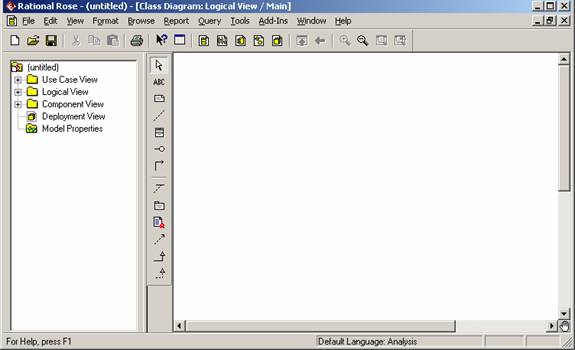
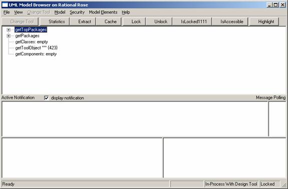
CHANGE NOTIFICATIONS Figure 1 depicts Rose after startup. The diagram is blank except for some default elements such as the “Logical View” package. Press F11 in Rose to open the UML Model Browser window (Figure 2). This browser window is an add-in to Rose we built to illustrate the two services of the UML Interface.
Figure 1. IBM Rational Rose after startup (the model is blank)
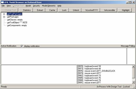
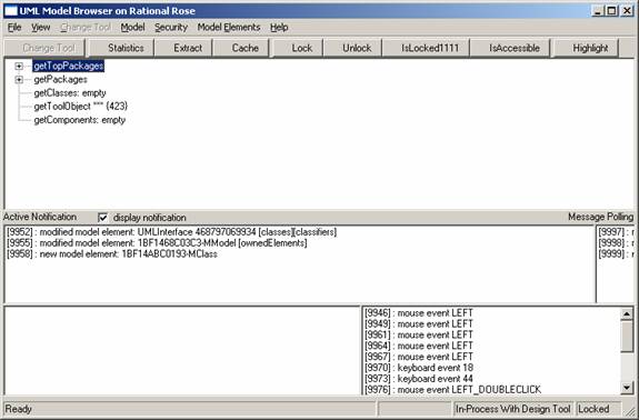
Figure 2. The UML Model Browser illustrates the two main services of the UML Interface To illustrate change notification, consider the following user activities within Rose. The simple-most activities of a user in Rose are to click with the mouse or type with the keyboard. If you do so in Rose then UML Interface observes these activities and forwards them to the model browser (and interested listener). Figure 3 (bottom right) shows such keyboard and mouse events as observed through the UML Interface.
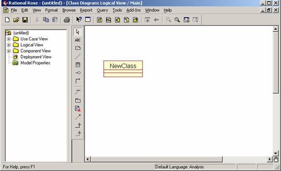
Figure 3. Keyboard and Mouse Events in Rose observed by the Model Browser Keyboard and mouse events are the basis on which we reason about model changes inside Rose (see [5,6]). They are used to guide and optimize caching and comparison activities between Rose and the UML Interface. The user of the UML Interface (e.g., the Model Browser in this case) is not aware of this complexity but is able to consume the resulting change observations in an easy to understand format. For example, if you create a class in Rose (Figure 4 top) then this activity is normally not observable from other tools (e.g., such as the model browser). That is, while Rose has an API for reading its model state, it does not have an API that tells about changes to its model state. User changes are thus not observable from the outside and tools that consume Rose model data are thus not able to observe these changes. The UML Interface, however, externalizes model changes of Rose. These changes become observable to tools, such as the Model Browser, and these tools may trigger subsequent analyses or syntheses if so desired (e.g., incremental transformation and analysis). Figure 4 (bottom) shows the model browser where its middle panel displays a set of model changes from Rose. We observe that a new model element of type MClass was created (this is a UML Class). Also a model element of type MModel was modified. This message refers to the fact that, in Rose, the creation of a class also triggers the modification of the model (package) that owns it. That is, the new class is implicitly owned by the “Logical View” package which thus changed in its list of owned elements.
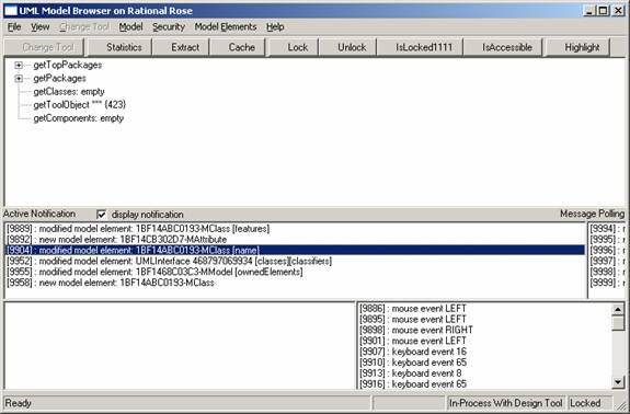
Figure 4. The Creation of a Class in Rose is observed by the Model Browser Changing the new class into a class with the name “A” results in the message “modified model element: ???-MClass [name]”. Or adding a new attribute to the class results in the two messages: “new model element: ???-MAttribute” and “modified model element: ???-MClass [features]. Figure 5 displays these changes. Thus, the creation of an element results in a new model element message and the modification of an element results in a modified model element message. Since the modification may only affect some of the properties of an element, the modification message also tells what properties got modified (e.g., [name] or [features]). In addition, the message contains the unique id (e.g., hex string), time stamp, and other vital information. Note that a “feature” is the UML lingo for the list of attributes and methods of a class. Thus a new attribute was created which modified the list of features of the class.
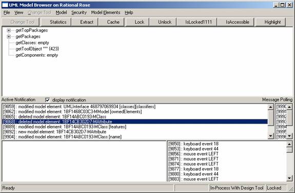
Figure 5. Modified Class Name and New Attribute The deletion of the class in Rose not only deletes the class but also its feature (e.g., attribute). Plus it modifies the “Logical View” model as it no longer owns the now deleted class. See Figure 6 for the detailed list.
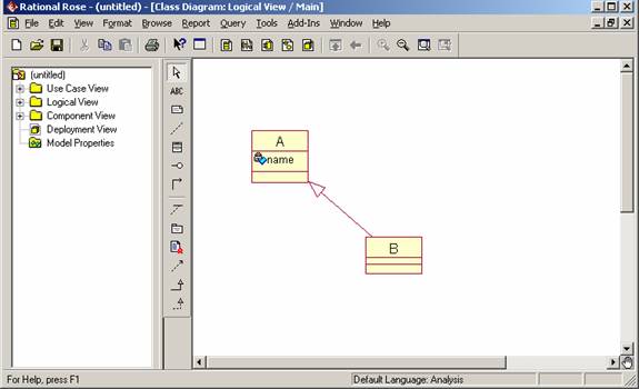
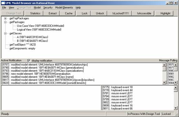
Figure 6. Deletion of Class with Attribute The UML Interface not only displays changes of class diagrams but also of package diagrams, use cases, and state chart diagrams. However, it does not display changes of the sequence, activity, or component diagrams. UML ACCESS As was said earlier, the UML Interface is not only about externalizing changes to Rose. It also provides an UML 1.3 compliant way of accessing Rose model data. Figure 7 (top) displays a little model with two classes and one relationship. This information may now be accessed in an UML-compliant way by using the classes and methods of the UML Interface. Since we do not want to show code pieces, we built the Model Browser to provide instant access to all “get” methods of the UML Interface. For example, the UML Interface provides a top-level “base” class that returns, among other things, the list of classes or packages (models). Figure 7 (bottom) displays the result of this query in the top panel. That is, the model browser displays the two default Rose packages and the two classes we just created (class A and B).
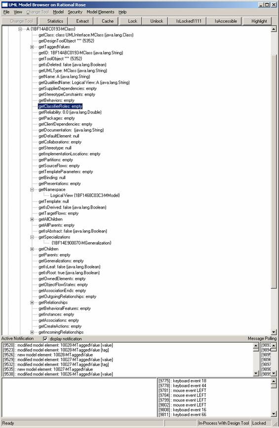
Figure 7. Navigating the Rose Model the "UML-Way" To see what information the UML Interface provides about class A, double click on its entry in the model browser. It expands by listing its properties such as its class type (a UMLInterface.MClass), its unique id, or its name. We also see that the class is owned by “Logical View” (i.e., namespace).
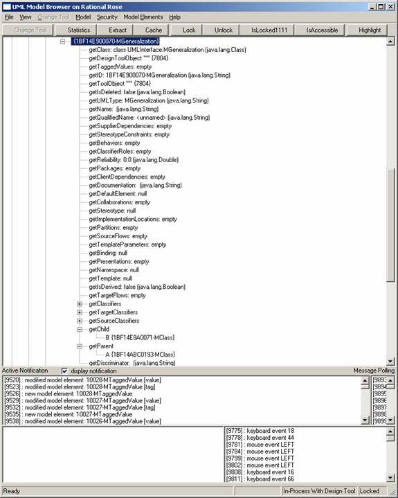
Figure 8. Navigating the Class A We know from the Rose model in Figure 7 (top) that class A has a child called class B. In UML, the specialization property points to a Generalization type that defines this parent-child relationship. This relationship can be accessed by double-clicking on the MGeneralization element in the getSpecialization field. Figure 9 lists the properties of this relationship which includes, among other things, the values for getChild and getParent (e.g., B and A respectively).
Figure 9. Generalization Relationship between Classes A and B The UML Interface is capable of reading class, package, use-case, sequence, and statechart diagrams. It cannot read activity and component diagrams. BACKGROUND: The Unified Modeling Language (UML) The Unified Modeling Language (UML) is currently the leading object-oriented analysis and design model. It supports a variety of design views, some of which object-oriented in nature (e.g., class diagrams [1] [11]) and others more functional (e.g., statecharts [8]). For the most part, views in UML are graphical; however, there are also textual descriptions, mostly in the form of add-ons to the graphical notation (e.g., Object Constraint Language [13]). UML is the result of a collaboration between numerous companies and OO modeling experts and it borrows heavily from Booch [1], OMT [11], and other OO models such as [3], [4], and [9].
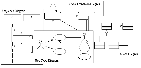
Figure 1: Some of Diagrammatic Views support by UML “UML is a language for specifying, visualizing, constructing, and documenting the artifacts of software systems, as well as for business modeling and other non-software systems” [2]. These different but overlapping uses of the model can only be achieved by supporting a variety of graphical representations. UML thus defines over 150 types of elements to support eight types of diagrams. The eight diagrams are class diagrams, sequence diagrams, statechart diagrams, use case diagrams, package diagrams, deployment diagrams, collaboration diagrams, and activity diagrams. Some of those diagrams are schematically depicted in Figure 1 showing a sequence diagram (left), a class diagram (right), a use-case diagram (middle-bottom), and statechart diagram (middle-top). The diagrams are discussed below briefly. A more detailed discussion of UML diagrams is outside the scope of this thesis. We assume the reader to be familiar with the basic UML design concepts. Please refer to [12] or the “OMG Notation and Semantics Guide for UML” [10] for more detailed descriptions (this work uses UML version 1.3). Additionally, [7] provides a brief overview of UML.
REFERENCES [1] G. Booch. Object-Oriented Analysis and Design with Applications, Addison-Wesley, 1994. [2] G. Booch, J. Rumbaugh, and I. Jacobson. The Unified Modeling Language User Guide, Addison Wesley, 1999. [3] P. Coad and E. Yourdon. Object-Oriented Analysis, Yourdon Press, 1991. [4] P. Coad and E. Yourdon. Object-Oriented Design, Yourdon Press, 1991. [5] A. Egyed and B. Balzer, Integrating COTS Software into Systems through Instrumentation and Reasoning, Journal on Automated Software Engineering (JASE), vol. pp. accepted for publication [6] A. Egyed and R. Balzer, "Unfriendly COTS Integration - Instrumentation and Interfaces for Improved Plugability," Proceedings of the 16th IEEE International Conference on Automated Software Engineering (ASE), Nov. 2001. [7] M. Fowler. UML Distilled: Applying the Standard Object Modeling Language, Addison-Wesley, 1997. [8] D. Harel, Statecharts: A Visual Formalism for Complex Systems, Science of Computer Programming, vol. 8, 1987. [9] I.M. Jacobson, M. Christerson, P. Jonsson, and G. Overgaard. Object-Oriented Software Engineering : A Use Case Driven Approach, Addison-Wesley, 1992. [10] OMG. Unified Modeling Language Specification Version 1.3, OMG, 1999. [11] J. Rumbaugh, M. Blaha, W. Premerlani, and F. Eddy. Object-Oriented Modeling and Design, Prentice Hall, 1991. [12] J. Rumbaugh, I. Jacobson, and G. Booch. The Unified Modeling Language Reference Manual, Addison Wesley, 1999. [13] J. Warmer and A. Kleppe. The Object Constraint Language, Reading, MA: Addison Wesley, 1999. |
||
|
|
||